
How to Choose Board Direction and Ventilation for Composite Cladding
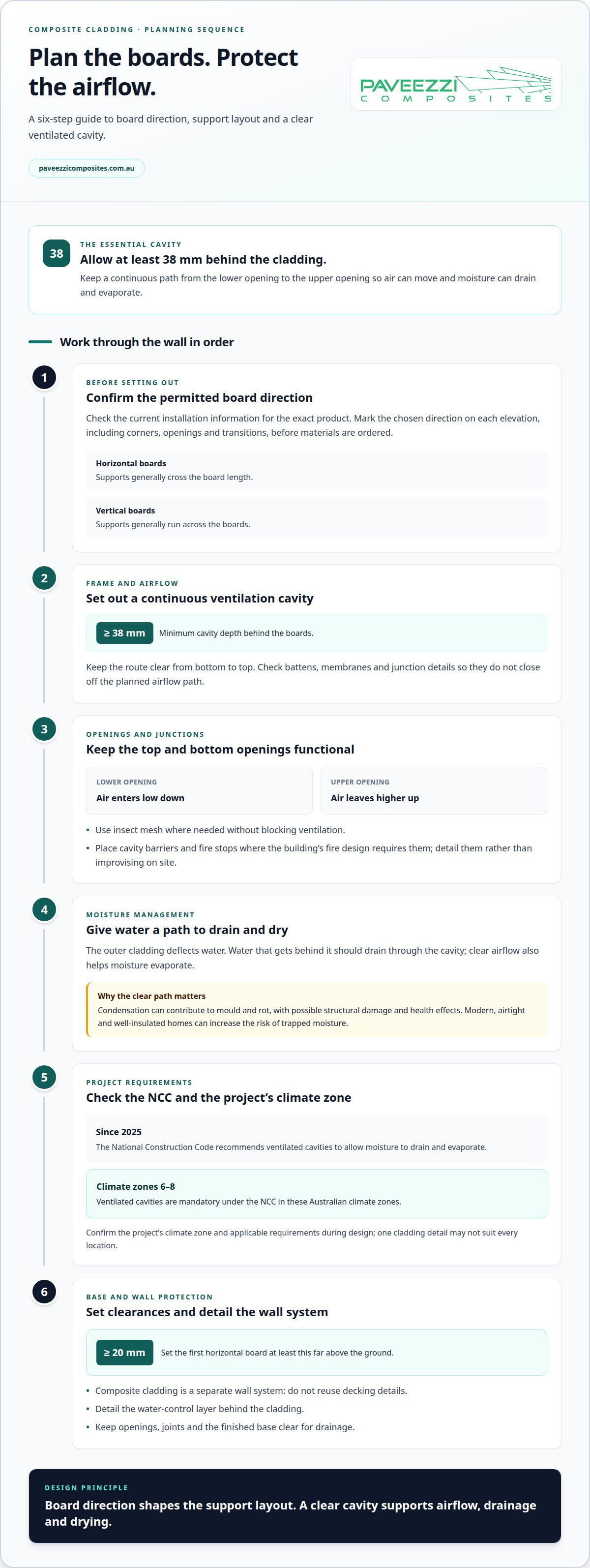
Board direction is a design choice, but ventilation behind the boards is essential. This composite cladding ventilation guide explains how horizontal or vertical boards affect support direction and frame layout, and why the cavity behind the cladding needs to stay clear. A ventilated cavity at least 38 mm deep allows airflow and drainage.
It’s easy to focus on the finished look: horizontal boards create one visual rhythm, vertical boards another. But orientation also determines batten layout and how air moves behind the cladding. Check the product’s installation instructions for permitted orientations and support requirements.
This composite cladding ventilation guide explains how to plan board direction, set out the frame and keep ventilation paths clear around openings and junctions. The goal is to balance appearance with reliable support and airflow, allowing moisture to drain and dry behind the boards.
Table of Contents
Can boards run vertically or horizontally?
Yes, composite cladding boards may run vertically or horizontally when the selected product permits that orientation. In either layout, plan a continuous cavity at least 38 mm deep, with clear openings that allow air movement and drainage.
Confirm the permitted board direction. Check the current installation information for the exact cladding product before setting out the wall. Horizontal boards and vertical boards need different support directions, so the choice affects battens, joints and junction details. Draw the board direction on each elevation, including corners, openings and transitions. This makes the support layout clear before materials are ordered.
Set out a continuous ventilation cavity. Allow at least 38 mm behind the cladding boards. Keep the cavity clear from the bottom opening to the top opening, so air can move through the wall section. A ventilated cladding system uses that space to help moisture drain and evaporate. Battens, membranes and junction details should not accidentally close the planned airflow route.
Keep the top and bottom openings functional. Provide openings that let air enter low down and leave higher up. Fit insect mesh across openings where needed, without blocking the ventilation path. Place cavity barriers and fire stops where the building’s fire design requires them; detail these carefully so the specified fire protection works alongside planned drainage and airflow. Do not leave these components to be improvised on site.
Account for moisture and Australian conditions. The outer cladding deflects water, while water that gets behind it should drain through the cavity. Condensation can build up in the cavity and contribute to mould and rot, with possible structural damage and health effects. Modern, airtight and well-insulated homes can increase the risk of trapped moisture, making clear airflow and careful wall detailing important.
Apply the NCC requirements to the project. Since 2025, the National Construction Code recommends ventilated cavities to allow moisture to drain and evaporate. Ventilated cavities are mandatory under the NCC in Australian climate zones 6-8. Confirm the project’s climate zone and applicable requirements during design, rather than assuming one cladding detail suits every location.
Check clearances and wall protection. Set the first horizontal board at least 20 mm above the ground. Composite cladding is a separate wall system, so don’t reuse decking details. Detail the water-control layer behind it, then keep openings, joints and the finished base clear for drainage. Explore composite cladding options alongside the project’s required cavity design.
Keep the ventilation gap clear so airflow can help moisture evaporate. Condensation can lead to mould, rot, structural damage and health issues. Where ventilation is not mandatory, a ventilated cavity is often a straightforward pathway to NCC compliance.
Board orientation and support direction
Mark the board direction on each elevation. Before planning supports, draw whether the boards will run vertically, horizontally or diagonally. Horizontal boards generally need supports crossing their length; vertical boards need supports running across them. This affects the frame layout and where board ends meet supports. Mark corners, openings and material transitions on the same drawing, so each junction has a planned fixing position.
Match support positions to the cladding instructions. Support spacing varies by composite cladding product, so use the current installation information when marking battens. Show supports behind board ends and joints rather than leaving joints unsupported. Include window and door perimeters, where cut edges need suitable support and flashing details. This set-out also helps align screws with the frame.
Detail vertical or diagonal timber separately. For vertical or diagonal profiled timber boards in Australia, vapour-permeable sarking must comply with AS 4200.1. Adjoining sheets or rolls must overlap by at least 150 mm or be taped together. This timber requirement should not be transferred automatically to composite cladding. Keep the wall membrane and cladding system details distinct in the drawings.
Plan joints, corners and openings together. Position board joints over suitable supports, then show how corners and window or door reveals will finish. Allow for the water-control layer and flashings behind openings; the cladding surface alone does not detail these junctions. On the elevation, note changes in board direction and how the final board meets the perimeter. Resolve these details before ordering accessories.
Allow for board movement at fixings and ends. Composite boards can expand, so follow the product instructions for fastening, spacing and movement gaps. Don’t replace the specified detail with a tight hole or rigid fixing. Where a board meets a groove, corner or end joint, use the product detail to maintain the required movement.
Coordinate fascia boards with the cladding finish. A fascia, trim or board at the top or bottom can restrict movement if it traps the cladding edge. Set out the termination so the required gap remains, and make sure the finish does not block drainage or ventilation openings. Record the edge detail alongside the board direction. For a broader view of composite surface options, consider how the cladding finish will sit with the rest of the project.
Composite cladding orientation affects support direction and junction details. Before finalising the set-out, confirm permitted orientations in the current product information.
Does Vertical Cladding Need a Different Frame Layout?
Yes. Vertical boards need supports arranged to suit their direction, while the frame must still provide a stable fixing base and continuous drainage paths. Plan battens, openings and corners together.
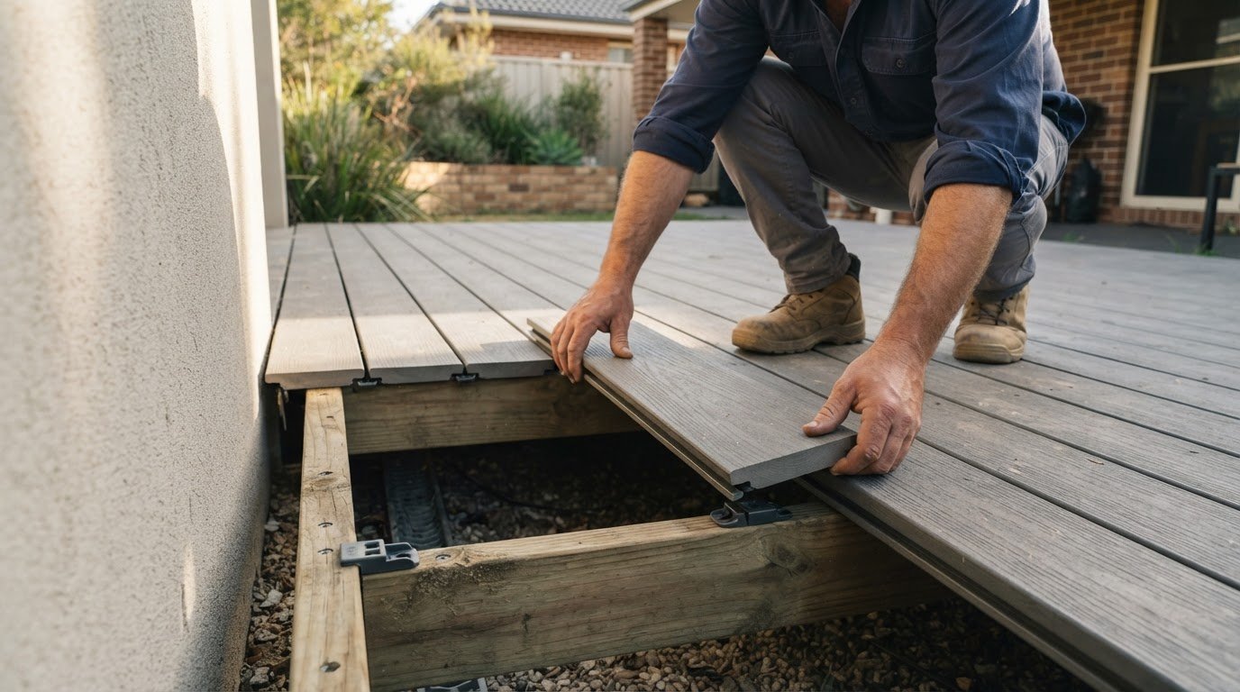
Select frame and batten materialsStart by identifying the wall substrate and the support framework needed to secure the cladding. Choose frame and batten materials to suit the wall and expected weather exposure. Don’t treat decking joists as a substitute for a cladding subframe: wall systems have different fixing and moisture-control requirements. Record the substrate, proposed supports and weatherproofing responsibilities before preparing the material takeoff.
Set batten spacing and alignmentMark batten positions using the current installation information for the exact composite cladding product. Keep each batten straight and aligned, since uneven supports can affect board fit and the finished surface. Composite cladding support battens should be fixed at intervals no greater than 600 mm, with each batten fixed in at least 3 places. Keep the first support batten at least 20 mm from the ground.
Add counter-battens for vertical claddingUse a counter-batten arrangement where the underlying support direction cannot directly support vertical boards and maintain the required cavity. One batten layer can provide the fixing direction; another can create a clear route for airflow behind the cladding. Keep that route continuous, and don’t let intersecting battens or fixings obstruct drainage. For vertical composite cladding, the guide recommends battens with a 15° tilted top edge to shed water and reduce pooling.
Set out openings and corners. Add supports around doors, windows, board ends and material junctions so edges and joints have a suitable fixing base. Mark their positions before installing battens. Plan how the frame meets each reveal and corner while preserving the ventilation path and allowing water to drain. Detail opening flashings as part of the junction, rather than relying on cladding boards alone to manage water.
Match fixings to the specified system. Follow the selected product’s installation details for fastening and support spacing. Don’t assume one screw type suits every board direction or frame material. A specified horizontal cladding installation uses 8-gauge, 38 mm A2/A4 pan-head screws, with screw-head thickness no greater than 2 mm. Apply that detail only to the stated installation, not automatically to vertical boards.
Check the frame before covering it. Confirm that battens are aligned and firmly fixed, and that openings and corners don’t block the cavity. Photograph concealed supports and junctions before closing the wall. Record approved layout changes so the completed frame can be compared with the project details.
Ventilation behind composite cladding
Use this composite cladding ventilation guide to plan the cavity as part of the wall system, not as an afterthought. The installation method must account for drainage, airflow and the selected product’s instructions.
Establish ventilation behind composite claddingStart by identifying the wall substrate, water-control layer and support framework. Then map a continuous cavity behind the external boards, with air able to enter low down and exit higher up. Battens create the space, but poorly detailed junctions can interrupt it. Draw the cavity route through each wall section, including corners and changes in direction, before cladding installation begins.
Compare cladding ventilation approachesFollow the selected composite product’s instructions rather than assuming timber or fibre-cement details apply. Board profiles, fixings and junctions differ between systems. A practical composite cladding ventilation guide compares how each system manages water, movement and airflow, then coordinates its supports and details accordingly. Don’t combine methods from different products without considering how that changes the wall build-up.
Coordinate the cavity with the wall layers. Set out the substrate, water-control layer, battens, cavity and boards in sequence. The outer cladding helps deflect rain, while water that passes behind it needs a drainage path. Keep membranes and supports from sagging into the airflow route. Show the layers in a section drawing so the installation method is clear beyond the external elevation.
Detail openings and junctions before installation. Draw the cavity around windows, doors, corners and material transitions. Flashings need to direct water outwards while maintaining the ventilation route around each opening. Where the building’s fire design requires cavity barriers or fire stops, coordinate their positions with the wall details. Don’t remove or alter these components on site to restore airflow.
Keep the airflow path clear during cladding installation. Check that battens maintain consistent spacing and that offcuts, sealants or fixings don’t obstruct the cavity. Protect openings from insects and debris without sealing them shut. Before closing the external face, inspect the base, top and junctions. Photograph concealed supports and record approved detail changes for future reference.
Plan for moisture and upkeep. A cavity supports drainage and evaporation, but blocked airflow can leave dampness against the supporting wall. Condensation may contribute to mould and rot, affecting building materials over time. Keep visible openings clear of leaves, dirt and cobwebs. For a project-specific product selection, explore composite cladding options alongside the wall-system design.
Paveezzi Composites
Paveezzi Composites supplies composite cladding for residential and commercial projects. If you’re deciding on board direction, frame layout and finish, its cladding range can be considered alongside your wall design and ventilation plan. Use the selected product’s installation instructions to set out supports and fixings. Choosing the product early helps align the appearance with practical detailing.
For guidance on choosing cladding for your project, contact Paveezzi Composites.
Take your cladding plan to the next stage
Use this composite cladding ventilation guide as a starting point for turning your design intent into coordinated project drawings. Set the preferred board direction alongside support positions, junctions and the wall build-up, so the material schedule and installation details work together from the outset.
Paveezzi Composites offers cladding options including Cladding Ressisto 144 Fineline and Cladding Ressisto Lightissimo202, as well as Decking Ressisto 143 Brushed for outdoor projects. Considering the finish and material choices early can help you shape a cohesive exterior specification.
Bring your project requirements and preferred look into the next conversation. Contact Paveezzi Composites to discuss your cladding selection. A considered plan is a strong place to begin.
Frequently Asked Questions
Are 500 mm Centres Suitable for Every Project?
No. A 500 mm spacing is not a universal rule for composite cladding supports. Use the current installation information for the exact product, considering board orientation and the wall layout. The 500 mm figure in cladding guidance applies to battens separating and supporting boards in storage, not a general on-wall spacing. Distinguish storage requirements from the installed frame before setting out supports.
Can Cladding Boards Be Fixed Directly to the Wall?
In a ventilated cladding system, boards are fixed to supports rather than directly against the wall. Battens provide a fixing base and form the cavity between the boards and wall layers. Direct fixing leaves no cavity in this arrangement. For example, a wall with vertical boards may need supports across their direction. Follow the selected product’s installation instructions for the fixing method.
What Does a Cladding Subframe Do?
A cladding subframe creates the support plane between the wall structure and outer boards. It provides a firm base for fixings and can establish the cavity needed for drainage and airflow. For example, battens can support board ends and openings while maintaining the designed wall build-up. The subframe layout should suit the cladding direction, substrate and junction details.
What Happens When Airflow Is Poor?
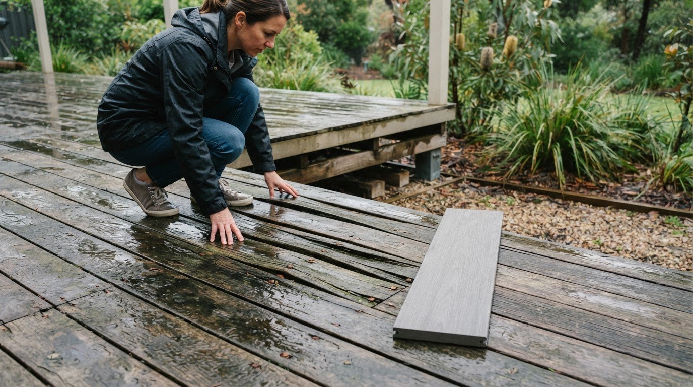
Poor airflow can slow moisture evaporation in the cladding cavity, leaving dampness against the supporting wall layers. Persistent moisture can contribute to condensation, mould and timber rot, and may damage the structure over time. A blocked opening or interrupted cavity can affect one section even when other areas remain ventilated. Clear debris from visible openings and keep drainage routes unobstructed.
What Is Cladding Ventilation?
Cladding ventilation is the movement of air through a cavity behind the outer boards. Air enters through lower openings, travels through the space and exits through higher openings, helping moisture drain and evaporate. The cavity also separates the cladding from the wall layers. For example, battens can create this space, while details around windows and corners must maintain the airflow route.
What ventilation gap is required behind composite cladding in Australia?
Allow a ventilation cavity at least 38 mm deep behind composite cladding. This space supports airflow and drainage, so measure the clear cavity behind the boards rather than assuming the batten size alone provides it. The National Construction Code makes ventilated cavities mandatory in Australian climate zones 6-8. Keep the cavity continuous, with openings and junctions arranged to support the designed airflow path.
Comments